INSTALLATION:
Before you start, read through these instructions carefully and check to see that you have the understanding, parts and tools needed to do each step.
I ONLY RECOMMEND NTK O2 SENSORS AND GENUINE MOPAR/JEEP SENSORS-
MAP, CKP-Crank Position Sensor, TPS, Water temp Sensor, CMP=Cam position Sensor.
PLEASE DO NOT USE CRAPPY CHINESE PARTS OR SENSORS. THESE ARE CRAP AND WILL CAUSE YOU PROBLEMS.
You are better getting used Junk Yard sensors than Chinese sensors.
You need a few special tools that will make this install much easier:
1: 5mm + 6mm "T' ball ended allen wrenches (Harbor Freight item #69084)
2: Fuel line quick disconnect (Harbor Freight item #97576)
3: RTV sealant for the plate surfaces (Harbor Freight item #90024)
Just to mention a few things before you get started.
-As most of the Jeeps out in the field have been modified in some way or another, some things might have to be done outside these instructions.
-Minor adaptations or modifications, if at all could be required
-Aftermarket/replacement/chinese parts ARE different that genuine stock Jeep parts. Fitment may vary. Example: different/replacement power steering pump may have a different diameter pulley.
-Bad Motor Mounts will cause the engine to shift usually to the drivers side and cause clearance problems. Replace bad motor mounts with MORE or Brown Dogs and not stock type mounts.
VACUUM LINES
The most confusing thing for most installers will be the vacuum and crankcase lines. What you have to remember is if it was hooked up to the stock intake manifold, it now hooks up to the s/c vacuum ports of the s/c just after the throttle body. Plugs are provided to fit into the 1/4" tapped holes in the stock intake manifold. The only exception is the 5/32" port. It may be on the side of the manifold or top. This port will see vacuum and boost. This will connect to the map (MAP) sensor and the Split Second box.
Regarding the factory map (MAP) sensor. The map (MAP) sensor will read manifold vacuum and pressure as it will see both boost and vacuum. This is critical to tuning the engine for boost and forcing the ecu into ‘open’ loop. On XJ side mount kit, mount MAP sensor on the intake manifold on small bracket and run hose from MAP sensor to intake manifold and to Split Second box so they see vacuum and boost. On th TJ top mount kit, mount the MAP sensor on the small bracket on top of the SC and run hose from MAP sensor to intake manifold and to Split Second box so they see vacuum and boost. .
The EVAP system needs to see vacuum. Imagine boost in your fuel tank! It is a 5/16 plastic line hooked to the manifold. On XJs it is on the passenger side and can be intercepted on the firewall. Cut it carefully so you can reinstall it with a short piece of hose. There is a small 1/8" hose to supply the heater system HVAC and the cruise control. Run the Brake Booster hose to fitting after the throttle body and before the supercharger(on the side of the SC).
On TJ’s it is located on the driver side. Use the same principles. You might have to bend the cruise control bracket.
On TJs you will have to bend the a/c lines. These are made of "O" hardness aluminum tubing. Do this before you install the s/c unit. Put the nose support in place and "gently" push the pipes down. Have someone hold the a/c lines down by the compressor using a wooden or plastic mallet to support. The lines are very malleable. Bend them gently so they do not touch anything on their way to the other side of the engine. If you are worried about the a/c lines contacting and rubbing, you can slice some heater hose lengthwise and place it on the a/c lines so that the lines do not rub.
VACUUM LINES-
*AFTER throttle body and BEFORE supercharger- HVAC, EVAP, Brake Booster, CCV/PCV, Bypass Valve top nipple(bottom nipple of bypass valve leave open to air)
*AFTER supercharger- MAP sensor, Split Second box
Optional- can try bypass valve top nipple to 'After SC' if experiencing boost leak due to opening of bypass valve due to higher boost levels
OBDII Scan Tool Bluetooth for ANDROID
Before you get started, read through these instructions carefully and check to see that you have the understanding, parts and tools needed to do each step.
Optional- can try bypass valve top nipple to 'After SC' if experiencing boost leak due to opening of bypass valve due to higher boost levels
OBDII Scan Tool Bluetooth for ANDROID
Plug ELM 327 into OBDII and turn ignition on, engine off
On you phone, go to 'settings'
turn on 'bluetooth', tap search for devices
should show up as OBDII, tap to pair
if asks for password, it is either 0000, 000000, 1234, or 123456. One of them will work.
Once paired, tap and open Torque PRO
go to Torque PRO 'settings'
'select device'
select OBDII
Go to gauge menu
start jeep
should see values,
also look for 'engine status' for closed/open loop operation
Before you get started, read through these instructions carefully and check to see that you have the understanding, parts and tools needed to do each step.
1: Remove the air filter box, XJs only, and rubber hose on top of the throttle body (T/B).
2: Remove the drive belt and the three power steering mounting bolts. You can let the pump hang out of the way.
3: Place a rag under the Schrader valve and de-pressurize the fuel rail via the schrader valve. Remove the steel fuel line, top and bottom, with the special disconnect tool. Use extra special care! Gasoline is very dangerous.
4: Remove the throttle cable bracket and cables. Tuck out of the way on the passenger side of the engine compartment. Watch the battery terminals!
5: Remove the throttle body (T/B), four bolts and the electrical plugs. Put some tape over or clean rag into the hole so you do not drop anything inside the manifold and engine!
6: Remove the vacuum fittings, intake air temp (IAT) sensor and any other vacuum pick up points. Install the ¼” pipe plugs. If you have a 5/32" vacuum fitting on the side of the manifold leave it in place for now. This is the best time to trim the original plastic hose and plan your vacuum routing.
Before you continue, read through these instructions carefully and check to see that you have the understanding, parts and tools needed to do each step.
Now we can start to install the new supercharger components.
7: Install the new s/c nose support. It goes in front of the stock power steering support. Put the 3 bolts back in and snug them up. Do not tighten them up yet. If you are doing a TJ with air conditioning this is the time to start modifying/bending the a/c lines.
8a: OPTIONAL-(instead of step 14) drill and tap manifold spacer and install intake air temperature (IAT) sensor pointing towards the rear. Connect wires to the IAT sensor. See picture. At this location the ECU will see true manifold charge intake air temperature (ChargeIAT) and you can monitor this with your OBD2 scanner.
8: Now to install the lower s/c mount plate and spacer. Remove the tape/rag from the intake manifold t/b bore. Use RTV to both sides of the spacer. Use the "t" handle to tighten the lower s/c mounting plate and spacer to the intake manifold with the supplied 6mm bolts.
9: Next, to install the upper s/c adapter plate. Place a clean rag into the hole leading to the intake manifold. CAUTION! It is real easy to drop the 66x10mm screws into the engine at this point. Use RTV on the top mating surface of the lower adapter plate and place the upper adapter plate (cut out opening towards the FRONT) onto lower adapter plate and start the 20 socket head cap screws. Remove your rag from the hole and make sure nothing fell into the engine. Tighten the bolts with the "T" handle. Cover the hole with a clean rag again.
10: Install the t/b adapter onto the s/c unit. Use RTV. Not the GM gasket. You need to seal of the EGR ports. Fit the Throttle Body to the t/b adapter with the throttle cable bracket mount plate sandwiched between two factory gaskets or RTV. See the picture to verify the correct orientation.
11: At this point you can test fit the s/c. No sealer. Now you can check the a/c lines, your vacuum lines and the plugs to the throttle body. Make sure all the t/b plug wiring is under the fuel rail except the air temp sensor.
12: Now you can finally fit the s/c unit. Remove the rag from the hole. Use RTV or the GM gasket. Either will also work fine. Use the "T" handles to tighten the bolts. By using these tools you cannot over tighten the bolts unless you are ‘super strong’. Six bolts are the same length, the longer one fits the stepped flange in the back of the s/c unit.
13: Now fit the electrical plugs onto the throttle body (TB). On later cars, the idle air control (IAC) will be tight.
14. (See Optional step 8a) Now for the cobra head air inlet 90 degree adapter. Depending on where your air filter is located, will determine where you install the intake air temp (IAT) sensor. Optional- Drill a 1/2 inch hole into the rubber cobra head adapter so that the intake air temp sensor points towards the valve cover. The drill will not leave a clean hole but the sensor will screw in just fine. Here you will see air temps before the s/c unit. The Split Second box is calibrated for this position.
Use the rubber spacer inside the cobra head adapter and fit it onto the t/b. Make sure when you tighten up the hose clamp the throttle shaft clears the clamp!!
15: Now connect the nose support bracket to the s/c unit using the link supplied to connect the bracket to the s/c unit. Refer to the picture to see how this is installed. Once all the bolts are snug, you can tighten the three power steering mounting bolts and the nose support link to the s/c unit.
16: Fit the idler pulley in place and install the belt. Do not overtighten the belt!! Use the factory specs. If you used one of our s/c units it has already had oil added.
17: Connect the brake booster hose to the location/barb provided on the side of the s/c unit.
18: Connect the CCV fitting on the top front of the valve cover to your air filter. This supplies filtered air to the engine for the CCV system.
19: Plug the new fuel line in place. Notice the provide clamp for the 7th fuel injector. Make sure the line stays clear of the exhaust and runs where the original steel line was fitted. Zip tie it in place as needed.
20: Cut off the one support leg to modify the stock cable bracket as seen in pictures and bolt in place. Attach cables.
This should finish the mechanical part of the install.
Please contact us for any changes you feel is needed to add or clarify these instructions.
Split Second FTC Installation
Split Second FTC Installation
The Split Second box is already programmed for your Jeep 4.0.
21: Find a suitable place to mount the FTC unit. XJs have a spot above the brake booster where you can mount the unit. TJs have a flat plate also under the brake booster. There is plenty of cable for both installs. Remove the engine control plug (black) from your Jeep's ECU computer, then plug in the Split Second male harness plug. Now plug the factory plug into the Split Second female plug. Attach the fuel injector connection. Make sure that you zip tie the extra wiring into a safe bundle out of harms way. Done!! True plug and play.
22: Turn on the ignition key, but DO NOT START! Look and check for fuel leaks. If no leaks, now you can start your engine. Make sure the belt is running true and in the right grooves. Check for vacuum leaks. Make sure the lines do not chafe on anything sharp.
23: Readjust the belt to factory specs as needed. It will take a few miles for the belt to finally take a set. So watch the tension!
For the first few miles watch for anything that does not seem right.
You should run 91 octane at lower altitudes. You can try mid grade at higher altitudes and if you hear no pinging, you can continue to use it.
I hope your install went well. Enjoy the BOOST!!
M62 XJ Side Mount Kit- MODIFICATIONS REQUIRED
I hope your install went well. Enjoy the BOOST!!
M62 XJ Side Mount Kit- MODIFICATIONS REQUIRED
 |
| M62 XJ Side Mount Power Steering Pump Bracket WHERE TO CUT |
 |
| M62 XJ Side Mount Power Steering Pump Bracket WHERE TO CUT |
 |
| M62 XJ Side Mount Power Steering Pump Bracket WHERE TO CUT |
 |
| M62 XJ Side Mount Power Steering Pump Bracket WHERE TO CUT |
 |
| M62 XJ Side Mount Power Steering Pump Bracket WHERE TO CUT |
 |
M62 XJ Side Mount Power Steering Pump HOSE NIPPLE INSTALL  |
 |
M62 XJ Side Mount Power Steering Pump HOSE NIPPLE INSTALL 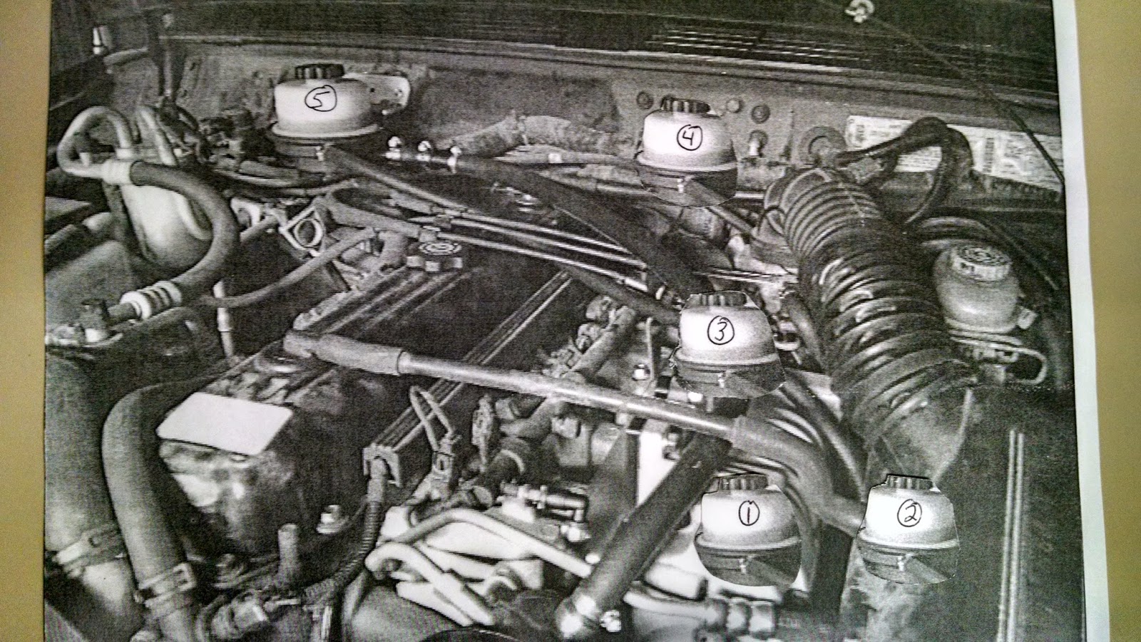 |
INSTALLATION TIPS:
VACUUM LINES/HOSES
After the Throttle Body and BEFORE the Supercharger
-HVAC
-EVAP
-CCV/PCV
-brake booster
-Bypass valve, TOP port (leave bottom port open to air to vent)
Intake manifold AFTER the Supercharger
-MAP sensor
-Split Second FTC-1
WIRE/ZIP TIE all vacuum hoses to seal and prevent blow-off
TEFLON TAPE all threaded fittings
BLUE THREAD LOCK all bolts
Use RED RTV on the intake manifold to head surfaces
Cut air intake hose and extend as needed with tubing and clamps
Use your stock Throttle cable bracket if you have Cruise Control
Use ECU/PLUG connector cover, wrap blue wires with tape as needed
POWER STEERING PUMP
-cut part off bracket as shown above
-remove reservoir
-BLACK RTV nipple and use 'tool' to insert into PS hole, See above, LET DRY!
-mount new reservoir near PS pump, see pic above #1 best, closest is BEST
-return hose to reservoir, FILL with PS fluid
Bend PS hard line GENTLY, don't kink, as needed
Use Fuel Disconnect TOOL to disconnect fuel line at fuel rail and underneath driver's feet
RECHECK belt tension after 1 day and 1 week of use
USE
-62mm Throttle Body for BETTER performance
-use NEW spark plugs and GAP 0.032"-0.035"
-use New O2 sensors as needed (from RockAuto, NTK best)
-use Rotella T6 Synthetic oil
SEE WEBSITE PICTURES FOR INSTALL HELP
SEE Build Threads on CherokeeForum.com Click '#becauseracejeep' and 'keepin it clean'
these are my 2 build threads, different but similar
E-MAIL ME ANY QUESTIONS
